SPEC 10037
QWIK Strip UF-B Copper Cable
Clean cuts. Fast installs. Fewer mistakes. All built into the jacket.
Underground Feeder Cable. 600 Volt. Sunlight, Moisture and Fungus Resistant Overall PVC Jacket
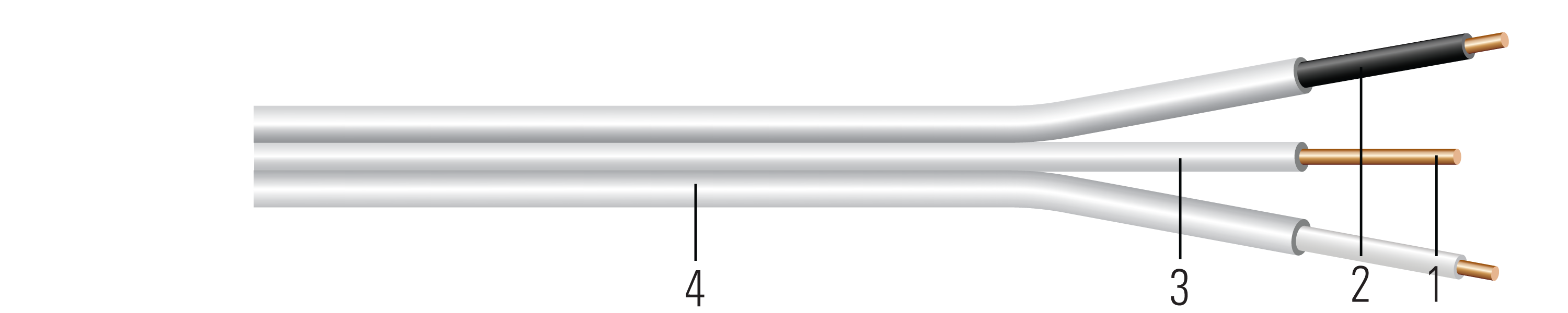

Construction:
- Conductor:Solid soft drawn bare copper per ASTM B3 or class B compressed stranded soft drawn bare copper per ASTM B8
- Insulation:All phases and neutral are insulated with Polyvinyl Chloride (PVC) with Nylon Sheath
- Ground:Solid soft drawn bare copper
- Jacket:Easy to strip white Polyvinyl Chloride (PVC) jacket. Sunlight, moisture and fungus resistant.
Applications and Features:
Southwire® UF-B Copper Cable with Qwik Strip™ Jacket is engineered for clean cuts, fast installs, and fewer mistakes. Precision-engineered grooves along the outer jacket serve as visual and physical cut guides, enabling accurate terminations with greater consistency and efficiency—no specialty tools required, and with reduced risk of conductor damage or installer injury compared to standard UF-B. This cable is ideal for use as a feeder to outdoor post lamps, pumps, and other loads or apparatuses fed from a distribution point in an existing building, as specified in the National Electrical Code® (NEC). It is approved for underground use, including direct burial, and may also be used for interior branch circuit wiring in residential or agricultural buildings at conductor temperatures not exceeding 90°C (with ampacity limited to that for 60°C conductors), per NEC guidelines. UF-B is also permitted in applications outlined for NMC in NEC Section 334.10(B). Voltage rating: 600 volts.
Specifications:
Sample Print Legend:
SOUTHWIRE QWIK STRIP(TM) UF-B E30445 (UL) XX AWG CU X CDR WITH XX AWG GROUND 600 VOLTS SUNLIGHT RESISTANT
Table 1 – Weights and Measurements
| Stock Number | Cond. Size | Conductor Number | Diameter Over Conductor | Conductor Stranding | Insulation Thickness | Ground Size | Jacket Thickness | Approx. OD | Copper Weight | Overall Weight | |||||||||
|---|---|---|---|---|---|---|---|---|---|---|---|---|---|---|---|---|---|---|---|
| AWG/Kcmil | inch | mils | No. x AWG | mil | inch | lbs/1000ft | lbs/1000ft | ||||||||||||
| 10 AWG | Solid | |||||||||||||||||||
| 458379◊ | 10 | 3 | 0.101 | Solid | 20/4 | 1x10 | 30 | 0.849x0.231 | 122 | 190 | |||||||||
All dimensions are nominal and subject to normal manufacturing tolerances
◊ Cable marked with this symbol is a standard stock item
TBA stock codes are estimations only and actual product may vary. Please wait until a stock code is assigned to purchase connectors and/or fittings.
Table 2 – Electrical and Engineering Data
| Cond. Size | Conductor Number | Min. Bend Radius | Max Pull Tension | DC Resistance at 25°C | AC Resistance at 75°C | Inductive Reactance @ 60Hz | Allowable Ampacity Raceway 75°C | Allowable Ampacity Raceway 90°C | |||||||||||
|---|---|---|---|---|---|---|---|---|---|---|---|---|---|---|---|---|---|---|---|
| AWG/Kcmil | Inches | Lbs | Ω/1000ft | Ω/1000ft | Ω/1000ft | Amp | Amp | ||||||||||||
| 10 AWG | Solid | |||||||||||||||||||
| 10 | 3 | 3.4 | 249 | 1.040 | 1.253 | 0.050 | 35 | 40 | |||||||||||
Ampacities based upon 2023 NEC Table 310.16 and do not take into account the overcurrent protection limitations in NEC 240.4(D) of 15 Amps for 14 AWG CU, 20 Amps for 12 AWG CU, and 30 Amps for 10 AWG CU (independent of the conductor temperature rating and stranding if size is present in table). Also, see NEC sections 310.15 and 110.14(C) for additional requirements.
Revision: 1.000.009
Updated On: Feb. 11, 2026, 4:28 p.m. UTC